Speckle has been a major obstacle for lasers to be used for display systems like laser projectors and other illumination purposes. It is usually quantified by the parameter ‘speckle contrast.’ Speckle contrast reduction became a major task for developers of these systems, in order to make displayed images ‘speckle free’.

With the need to increase the amount of light available for projecting movies onto larger screens; making projections sufficiently bright for 3D (with consideration of filter losses for the left and right eyes); and ensuring a low cost of operations and long life, high power lasers are a prime candidate as a light source. They replace the traditional short life arc xenon lamps. Thus, speckle contrast reduction becomes the bottleneck for the deployment of lasers for cinema projectors.
A speckle pattern is essentially an intensity pattern produced by the mutual interference of a set of coherent wavefronts. It occurs in diffuse reflections of the laser light and in scattering surfaces such as a projection screen, making displayed images unacceptable.
Among many known methods in speckle contrast reduction, the most common approach is to use rotating diffusers, which destroy the spatial coherence of the laser light. In simple terms, the diffuser creates continuous variations in the speckle pattern over time. When viewed by the user, the average of the speckle patterns within the retention period of the eye will be observed, lowering perceived speckle contrast. The stronger the diffuser and the faster the rotation, the lower the speckle contrast. On the other hand, a rotating diffuser for high power applications encounters major problems in heat sinking without having a massive diffuser; such a large diffuser would require a higher power motor, which reduces the reliability of the speckle contrast reduction system.
A new patent pending speckle contrast reduction system is being developed by Litech International, LLC with very positive results, using a stationary diffuser, with which heat sinking become less challenging. In addition, a reflective diffuser made on metal can also be used, such that heat sinking can be done with more traditional fan/fins heat sinks, or even liquid cooling at extremely high power applications. The approach to using a stationary diffuser requires the laser beam to be scanned onto the diffuser surface; the challenge is to keep the output laser beam on the same optical axis while the beam is scanning, such that the etendue is not increased unnecessarily. In addition, since the diffuser is stationary and is obviously, non-rotating, the output will also be polarized in the same way as the input laser beam, when a polarization preserving diffuser is used.
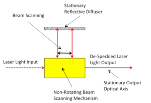
Figure 1 shows the functional diagram of the speckle contrast reduction system. The input laser beam is processed by a non-rotating beam scanning system, producing an output laser beamg. This moves back and forth perpendicular to the direction of the laser beam, scanning a line on the reflective diffuser as shown. The scanning laser beam is reflected by the reflective diffuser back to and re-processed by the non-rotating beam scanning system. This produces a diffused output beam with a stationary optical axis, regardless of the position of the scanning beam on the reflective diffuser. The divergence of the output beam is determined by the strength of the reflective diffuser. The total amount of speckle reduction is determined by the scanning distance on the reflective diffuser, the frequency of scanning oscillation and the amount of diffusion produced by the reflective diffuser.
Figure 1 – Functional Diagram of the De-Speckling SystemA preliminary experiment was performed using a red laser diode with a collimating lens and a transmissive diffuser, placed on top of a mirror, acting as the reflective diffuser. The scanning laser beam was driven by a triangular wave such that the scanning speed was constant on the reflective diffuser, with a frequency of about 30Hz. Both the amplitude of the scanning beam and the diffuser divergence were being varied and studied. Very encouraging results were obtained, as shown in Figure 2: scanning was “OFF” on the left, and “ON” on the right. The output of the laser beam was illuminating the backside of the photographic paper with random printed numbers (2095), as shown in the figure.
 Figure 2 – Picture of Output with Scanning “OFF” (left) and “ON” (right)It is clearly shown that the speckle image on the left is spotty and the numbers are not legible. With the scanning “ON”, the speckle image on the right is very smooth; the numbers are clearly legible and are exactly the same way as they are printed on the back of the photograph paper.
The apparatus for measuring the spectral contrast is being set up and there is a continuing effort in optimizing and improving the system using different kinds of diffusers, as well as varying the frequency and amplitude of the scanning with the contrast ratio as a guide. In the field of speckle contrast reduction, measured values are as important as visual experience. SEEING is BELIEVING. Shippable prototypes for evaluation are available for purchase from Litech International, LLC.
– Kenneth Li
Ken can be contacted at [email protected]