I’m still catching up with all the news from a lot of virtual events over the last few weeks, but here’s my second article from the Electronic Displays Conference in Nuremburg. I’m covering a talk by Xiaoxi He of IDTechEx, an industry analyst and her subject was the ‘Technical and Commercial Trends for MicroDisplays and Quantum Dots’ – hot topics at the moment.

 Ms He ‘didn’t take prisoners’ in her dive into the technology and I had to do a bit of digging to understand what she covered, but I think (and hope!) that I got there. She started by saying that while it’s widely understood that microLEDs are capable of high efficiency, beyond other technologies, those advantages can disappear when pixels are very small. The LEDs are also less efficient at low current density which may limit their advantages. These two factors make OLED more competitive for small displays than for large ones.
Industry maturity and cost are also big barriers on the supply side. There are two broad approaches to developing the market. You can try to replace current displays (LCD/OLED/LED) but could also create new markets and applications, exploiting, for example, the modular architectures that are possible with LED.
Ms He explained that one of the key problems is that the RG and B LEDs perform very differently and that makes building full colour performance very challenging. For example, blue is much more efficient than green or red. The different colours really need different materials and are grown on different substrates. That poses challenges in issues including, for example, variable threshold voltages.
There is a ‘green gap’ problem that comes up. In order to get a green colour using Indium Gallium Nitride, you have to have a high level of indium doping but this may cause an increase in the lattice mismatch and you can add polarisation which can cause the quantum confined stark effect (QCSE) (at this point, she got beyond my pay grade for LED physics!) and that reduces the EQE significantly. On the other hand to get a balanced white, you need a high level of green.
For red, which has the lowest External Quantum Efficiency (photons out for electrons in – EQE – ed.), you can use aluminium gallium indium phosphide (AlInGaP) but there are some challenges although this is the mainstream for commercial LEDs. It has a higher surface recombination velocity compared to InGaN. Longer minority-carrier diffusion length is in the range of micrometers rather than nanometres as it is for InGaN. That also means a high level of indium doping which may cause further lattice mis-match.
Different lateral or vertical structures or even flip-chip can be used, meaning more variables.
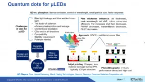
To make full colour, there are several strategies, e.g.:
- direct RGB,
- use colour filters (like LCDs) or
- colour converters.
Optical lens synthesis can also be used to combine RGB light and was first shown by Hong Kong University and is mainly used for projection displays.
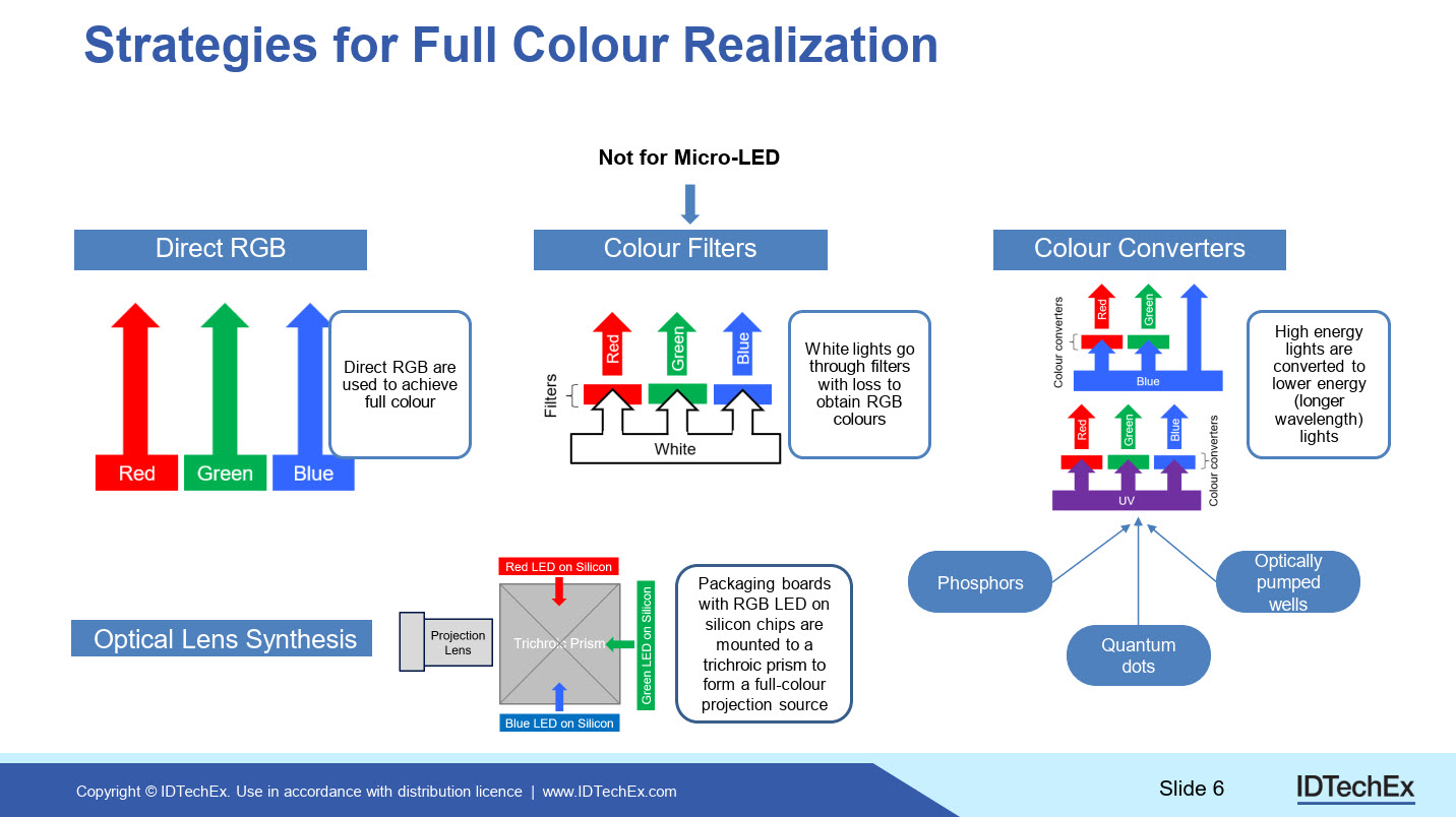
Colour Conversion
Colour conversion techniques use a single colour to create the light, then create it to full colour. Colour converted LEDs can be driven by blue or even UV LEDs (as used by MicroNitride of Japan) and the materials for conversion can be Quantum Dots (QDs), phosphors or optically-pumped wells.
Colour conversion can cause issues because of different material response times if the blue is used directly by emission. That can be solved by using UV LEDs and converting even the blue.
At the moment, direct RGB and QD conversion are the most popular paths for developers, but they are both very difficult. Driving the three different LED types is really tricky because of, for example, different drive voltages. Using just blue and with colour conversion from blue for the other colours reduces that complexity. Transfer of the LEDs from the manufacturing substrate may also be easier with a single architecture.
If you use phosphors, you may have challenges in spectral broadness and asymmetry, response time and ‘huge’ particle size (relative to the microLED). The red phosphors may also be less efficient than QDs.
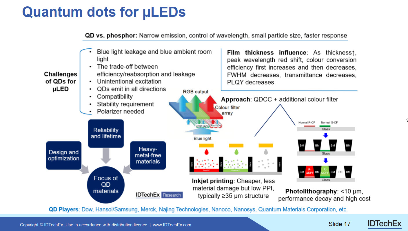
Looking at QDs, Ms He said, they are can have an adjustable bandgap, broad absorption combined with narrow and symmetric emission. You may be able to use the same material for emission and conversion and that is an advantage.
Ms. He looked more widely at QDs in photo-luminescent applications. Sony started with QDs in 2013, with QDs in a tube near the LED, and this changed to using film-based conversion. The latest QDs from companies such as Nanosys are less susceptible to damage from the environment and do not need the same level of barrier layers as they did in the past, so TCL, for example, uses what it calls a QD diffusion plate, rather than using the QDEF name.
There has been some development of putting QD onto glass, as used by HP in a monitor (Will QDOG Have its Day?). There was work on replacing the colour filter with QDs, but Ms. He skipped over it. You can also put QDs on to the LED chip directly (although there are challenges with heat there – editor). QD is also still in a relatively early stage of development.
In microLED, you can use QDs as a conversion layer. The blue may need an optical layer to match the optical characteristics of the other colours.
QDs have the advantage of fast response and tunable colour with a narrower FWHM but may allow some blue light leakage or may react with blue ambient light. Adding more QDs may solve the leakage problem, but there is a trade off between efficiency and reabsorption/leakage.
(I’m reminded that when Philips Lighting told me about its HLD green conversion system for projectors, it told me that the biggest challenge was in avoiding (or limiting) the reabsorption of the light you want, rather than in the conversion Philips’ HLD Technology Offers Compelling Value Proposition– Editor)
Further, there can be unintended excitation of one colour by another – for example, the green light may excite the red pixels. QDs emit the light in all directions and that needs to be managed. There are also challenges in patterning and stability.
Because the most efficient QDs use cadmium, other materials are being investigated for colour conversion. In particular metal halide perovskites, which are not as restricted as for ROHS reasons. (for more see Cadmium-containing QDs are on the Chopping Block – RoHS update 2021)
The conversion materials can be deposited using photolithography or inkjet printing, for example. Inkjet printing may need plenty of QD material to avoid leakage, which can be an ROHS challenge for cadmium-based materials. (and can also be a cost issue – QD materials are not cheap – Ed.)
However, QDs can be deposited in small dots and Ms. He showed number of examples of very small QD patterning from 3 microns to hundreds of microns.
In summary, there are advantages and challenges still in QD use for microLEDs. (BR)